PretensT
Tensegrity is a special kind of structure made of push and pull.
Project maintained by elastic-interval Hosted on GitHub Pages — Theme by mattgraham
Compression Column
In the previous project we encountered axial tension, which created a surprising stiffness in a tensegrity column. Ultimately we even ended with the idea of making the ends of the column come to a nice point!
When you have an axial tension columnn in your hands and you compress it end-to-end, you realize that as a whole it’s basically the same as a compression element, with a specific set of characteristics. It pushes back. That prompted me to imagine creating a kind of macro-tensegrity where an axially compressed column becomes the compression member.
This is effectively the first step towards imagining a tensegrity fractal where every compression bar is actually a tensegrity itself, and you end up ultimately with a seemingly absurd large structure with only tension all the way down to the microscopic.
There’s a reality check when the imagination runs wild like this, and that’s to see what it is like to build at least one level of the fractal tensegrity.
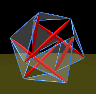
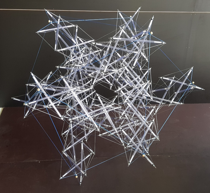
Each one of these red bars needs to be replaced with a column of tensegrity.
New Technique
The very daunting challenge that comes with such a fractal experiment is the sheer number of elements needed! Just making one pointy pretenst column takes some time, and each one requires a large number of identical parts.
Everything gets multiplied, so somehow we need an improvement to the efficiency of building. Previous structures have been quite labor intensive because each part took quite a bit of time.
We explored how to get quick at creating tension segments with Dyneema cord, and came up with something that accelerated the process a lot.
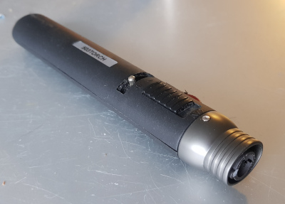
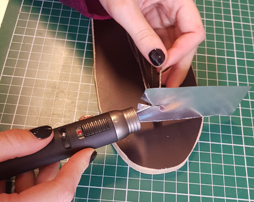
First, there needed to be a way to introduce intense heat very briefly and very quickly, so for very cheap we got a “QIANGUANG® Jet Flame” blowtorch which produces a nice sharp blue flame.
The problem still remains that when you go to heat up the end of the cord to make a thick end, you end up damaging all of the nearby cord as well.
For that we came up with a very simple solution, cut and bent from a small rectangular piece of thin metal: a do-it-yourself heat shield!
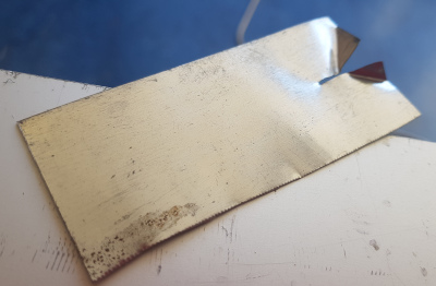
By allowing about 6mm of Dyneema to stick out of the slit in the heat shield, the result is a beautiful thickening at the end of the cord, almost like the head of a nail!
Better yet, you can get really quick at it.
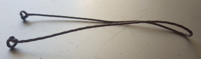
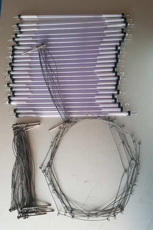
What we needed was very very many cord segments with in a loop at both ends. But also, the loop had to be made so that it didn’t become a strength vulnerability, and it also had to be quick to make.
It turns out that when you have created a nail-head end of the cord with the blowtorch and heat shield, it’s easy to make a single simple knot at the end which simply will never slip loose! You get the full strength of the cord.
Next step for creating large numbers of these was to create an extremely simple jig consisting of two beheaded nails in a piece of wood. Of course the distance between the nails is critical!
The process, in which we soon became very proficient, involves first creating two knots around the nails.
Then cutting the cord to leave 5mm or 6mm extra for melting the end, and slipping the heat shield over the end to protect the rest of the cord.
In less than a second, the blowtorch causes the cord to ball-up at the end, and you can quickly remove the flame, and pull away the heat shield. Then all that remains is pulling the knot tightly over the nail.
When the knotted cords are pulled upwards off the beheaded nail, there remains a beautiful hole. The loop hole is perfect, but it’s kind of vulnerable, so to preserve it we slipped them onto pairs of identical nails (not beheaded).
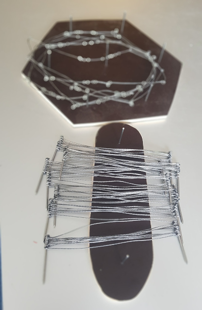
For each twist, a set of 9 loop-to-loop cord segments were needed so we grouped them together as such.
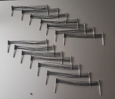
Not only is this a rapid technique, it’s also remarkably accurate. You could tell that the hole-to-hole distances were very nearly identical because all 9 cords could be pulled tight at the same time between the nail pairs.
This was the technique I had been searching for already for a half year! Fast and accurate.
What we also needed was actual tension loops for around the tensegrity column, each with 6 evenly spaced loops, so these were made with another jig with 6 beheaded nails.
So the cords are quick and easy to make, but what will the loops at the ends actually connect to?
Bar Ends
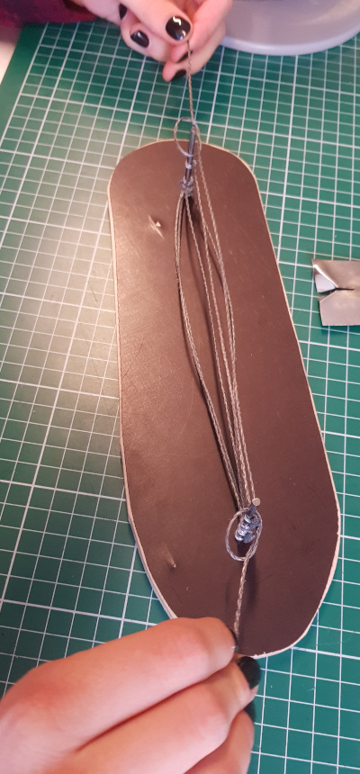
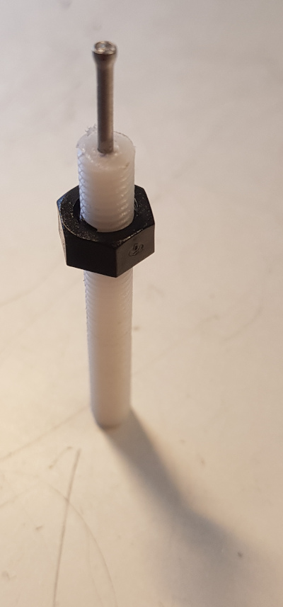
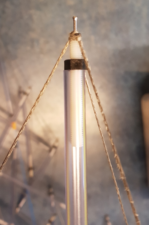
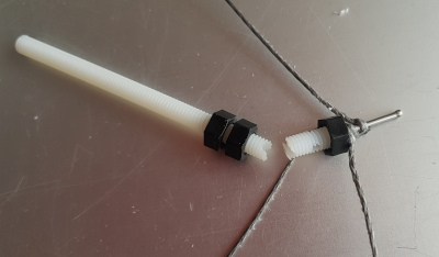
The ends of the bars have to allow for us to slip a number of loops over top, and as usual, we need the effective bar length to be extensible by turning nuts.
Once again, like in the first column we made, we will use the nylon threaded rod. Not so much because it’s the ideal material, but more because we still have a bunch of it left from the previous project.
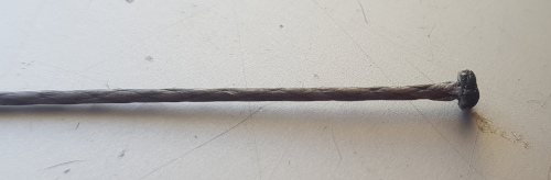
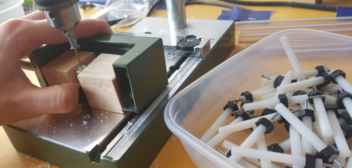
The necessary shape is created by drilling a little hole (1.4mm) in the end of the threaded rod, and then tapping a nail into the hole.
Needless to say, we had to make very many of these (276). Fortunately I had some help from my daughter.
To make the drilling easier and more accurate, we clamped a metal nut between blocks of wood. This way we could screw and unscrew every new one, and it would be held at the right place and straight up.
So now with the bar ends constructed, we just need the bars themselves. There was still enough length of clear PVC pipe left, so we cut many bars (138).
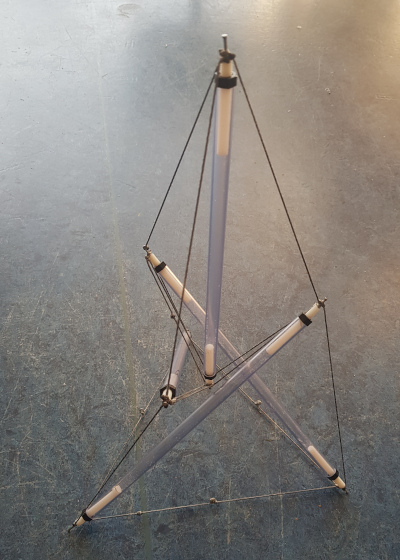
We finally had all the parts assembled, so we could build the first axial tension colummn, which was to become the first compression element in the higher-level tensegrity.
We started with a few experiments, to make sure that everything worked.
Yes, it was looking good.
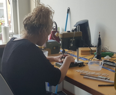
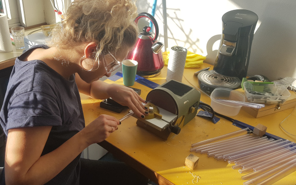
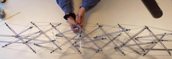
Four Robot Hands
Now, we had to build six of these columns, so it was important to get the process as refined as possible. If you are not able to do these things efficiently, you end up feeling like it’s simply costing too much time, even if you’re listening to music at the same time.
More importantly, this time I wanted to see what it was like to build using four hands instead of two.
Take it from me, it makes a world of difference to work with 4 hands! (Thanks again to my daughter for helping)
Axial Tension
With the column constructed, we strung a tension cable from one end to the other, and used a twisting trick to tighten it up to get just the right measurement of its ultimate length.
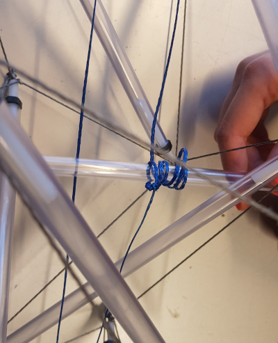
Once we had one that was exactly the right length, we had our first completed pointed column!
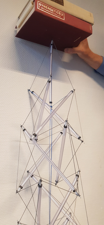
As far as carrying weight goes, it was able to pass the Synergetics Test, but barely. There was a hint of a problem in that the point was the first thing that appeared to give, but I ignored it for now.
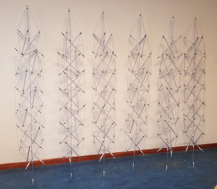
That Times Six
Above you see us working as robots to build one column, but of course we needed to build six of them. We just got to work, and piled them up when we were done.
Then finally, after a couple of days of robotic work (except for the music playing in the background) we had our tensegrity compression bars!
Assembling
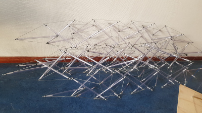
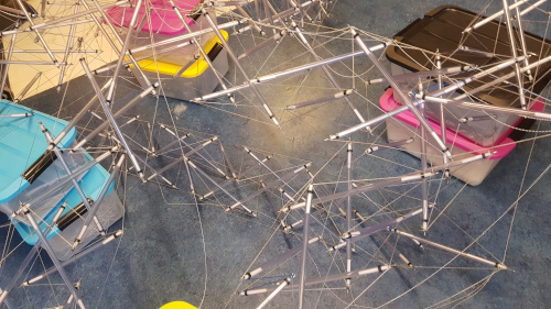
Assembling the macro tensegrity with the micro tensegrities was a remarkably difficult challenge, in part because it was hard to get the connections in place and the lengths right.
We were balancing things on crates, connecting and reconnecting, first with elastic cord.
Perhaps it was just stubbornness but I wanted to first get a feel for how it would work by using elastic. We were able to get the pointy ends connected in the right way.
The elastic cords were not pulling hard enough so we came up with a handy trick using a tie-wrap which allowed us to individually tighten the elastics temporarily, and adjust freely.
Even with this, the result was not very satisfying. A weakness was becoming apparent.
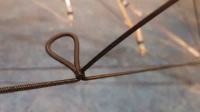
The nice looking point construction on the ends was clearly somehow inherently problematic. It looked so nice when we first tried it out!
Putting end-to-end compression on the points made the point bars tilt a little bit, which unfortunately immediately triggers the entire tensegrity column to bend in one direction, which causes the point bars to tilt even more.
The cascading effect was deadly for the kind of materials we’re using here (actually the stuff is too soft). Our first attempt at attaching the macro tension lines involved making holes in the end threaded rods, but that weakened them. Ouch.
But even aside from that, the awkward bending tendencies focused forces on the parts and it was just too much for these materials.
There were some gruesome disappointments, and fixing required.
We resolved to replace the pointed ends with a more stable approach which seemed much better at carrying the compressive force that needed to be present to hold it in shape.
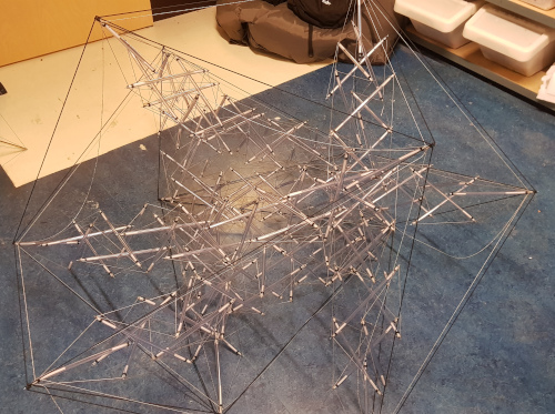
After removing the point bars at the ends of the columns, what remains is three tension cables inward, so we came up with a cute kind of connector which looked like it might work alright.
Finally we got it into a fairly nice shape but that required hanging it from the ceiling, because it really wasn’t strong enough to carry its own weight like this.
Not yet really satisfying, I had to admit. And it had all been quite the struggle.
Axial Hooks
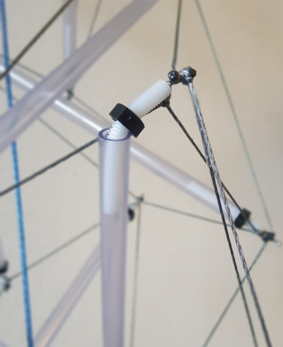
The new connection style on the column ends were much more capable of carrying the compression, since the intense tendency to curve and buckle went away after removing the pointy ends.
However the first connection trick didn’t really work well.
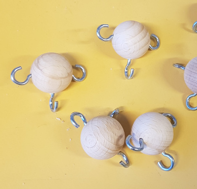
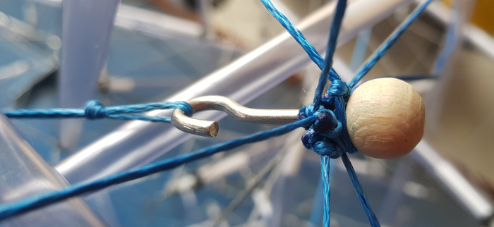
The next attempt involved a new kind of connection element made of hooks and wooden balls. Also we worked out the required lengths for the long cables and then went straight to un-stretchy Dyneema instead of elastic. Committing to the lengths helped.
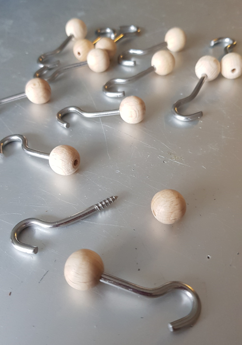
The long hooks could be used to attach to the three lines available at each end of each column, but they were also needed to hold the long macro tension lines which defined the structure as a whole.
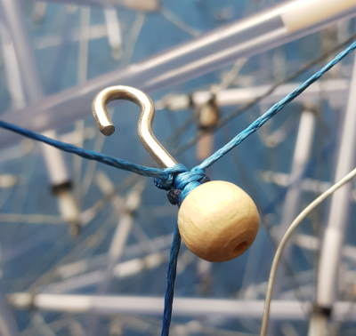
Finally, the hook itself could be used to connect up the axial tension from end to end.
Finally, it Stood
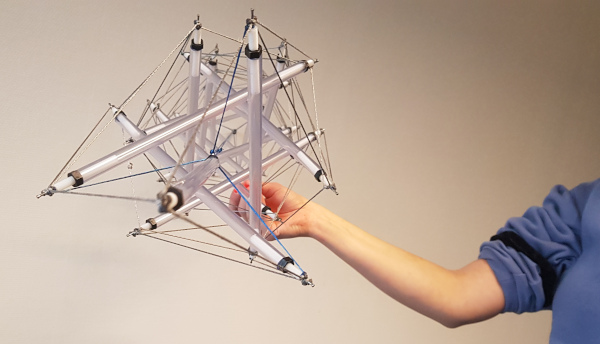
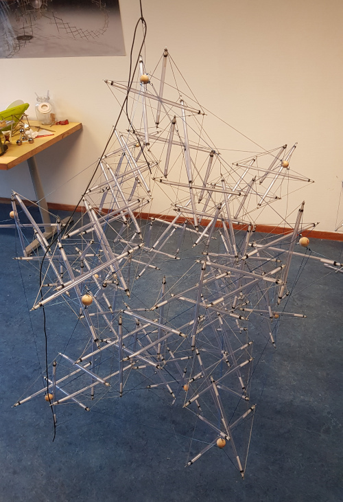
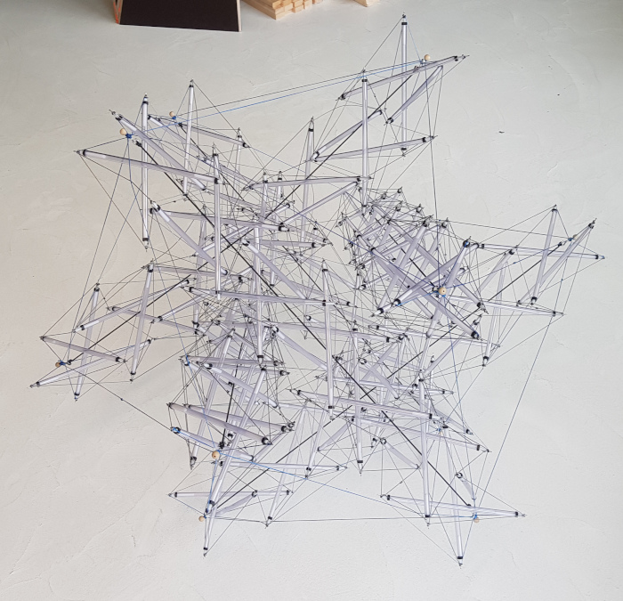
With these new hooks, and with macro tension lines at the proper length, it was finally possible to stand the tensegrity up properly.
The axial tension seemed to only play a minor role, so we replaced the tension lines with elastic cord instead, between the hooks at either end of each column.
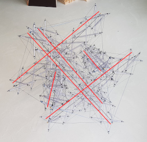
With a white background the elastic axial tension lines become apparent, and they actually correspond to the compression struts in the tensegrity, despite the fact that they are for tension.
Highlighted here:
Conclusion
Well, we managed to create a two-level fractal tensegrity structure where the higher level compression elements are themselves tensegrity structures!
Perhaps more importantly, we now have some new techniques which make building much faster and more accurate. This is going to come in handy!
As it turns out, the column elements are actually quite thick relative to the macro structure as a whole. Typically we just use solid or hollow cylindrical bars, which presumably have their microscoping tensegrity hidden from view, so they can be a lot thinner. Here the compression is tensegrity so you see it all.
It was extremely interesting to experience building the columns with 4 hands and to see that the pointed columns are not the right choice when it comes to strength, despite how pretty they might be. It could also be to a large degree that the materials used were just not strong enough in themselves to make it work perfectly.
Another surprise was how difficult it was to actually assemble the whole thing!
Many lessons learned! That’s what this is about, so…
Projects:
2024-07-23: "Bouncy Wooden Sphere": what you can do with a discarded bed2024-04-23: "Twisted Torque": tied into a permanent twist
2023-03-27: "Easy 30-Push Sphere": one simple element
2022-10-05: "Glass and LED": going big and colorful
2022-09-29: "Fascia": dancing with tensegrity
2022-08-30: "Mitosis": the four-three-two tensegrity
2022-08-04: "Push Bolts for the People": finalizing design and getting it out there
2022-06-22: "Head to Head Push Bolt": M5 and M6 bolts symbiosis
2022-05-30: "Hiding Knots": bump up the aesthetics
2022-05-25: "Innovation with 3D Printer": the push bolt
2021-12-02: "Headless Hug": breaking a rule for the sake of symmetry
2021-10-28: "Rebuilding the Halo": finally got it right
2021-10-20: "Convergence": growing and reconnecting
2021-07-27: "120-Strut Brass Bubble": taking the next step up in complexity
2021-05-26: "30-Strut Brass Bubble": bouncing spherical tensegrity
2021-04-08: "Bow Tie Tensegrity": better bend resistance
2021-03-29: "Six Twist Essential": what if more hands could see?!
2021-01-25: "Minimal Tensegrity": no more tension lines than absolutely necessary
2021-01-18: "Degrees of Freedom": first adjustable hybrid tensegrity
2021-01-11: "Fractal Experiment": a tensegrity of tensegrities
2020-12-09: "Axial Tension": pretensing what is already pretenst
2020-11-02: "Halo by Crane - Part 2": the strengthening
2020-10-26: "Halo by Crane - Part 1": assembly complete but strength lacking
2020-10-12: "Brass and Tulips": a tight and strong tensegrity tower
2020-08-10: "Prefab Tension Tower": the tower of eight twists
2020-07-27: "Elastic Bubble": building with elastic ease
2020-07-13: "The Twist Sisters": left-handed and right-handed
2020-07-06: "Radial Tension": Pulling towards the middle
2020-06-22: "Diamond of Tension": Four pulls for every push
2020-06-15: "Prefab Tension": Separating compression from tension