PretensT
Tensegrity is a special kind of structure made of push and pull.
Project maintained by elastic-interval Hosted on GitHub Pages — Theme by mattgraham
Challenge
I wanted to experience a tensegrity structure where the compression struts only push against the tension network, and I wanted to see how tight it could become. Typically the struts are drilled or slotted and the tension cables are used to make the final adjustments, but this became the first experiment involving a prefabricated tension network.
It was not easy, but this exploration with a prototype is supposed to lead to construction innovations to make the process more accessible. It was important to start by finding out how hard it is to build what I thought would work best, and would best illustrate the idea.
Model
I started by making a virtual model using the pretenst app, focusing on the joints where the tension cords come together. If the struts are to only push on the tension network, they must have something to push on, so I decided to make them spherical. This is an image of it ray traced by blender:
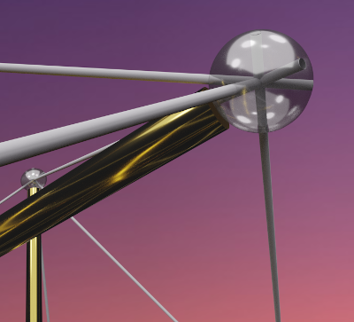
There is a potential conflict visible here because the cords all cross at the midpoint of the sphere, but I naïvely thought I could have them slide past each other in the middle somehow. Turns out it was a problem indeed, but I worked around it.
Plan
I really wanted to try out Dyneema cord, because it is super-strong, but also because it is hollow and made of 12 woven strands. I imagined wiggling a screw into the end of the cord and then tightening the screw to pinch the cord tightly against the inside of the hole.
A few experiments proved that this idea worked reasonably well, so I decided to give it a try. If I could get the balls-and-cords assembled first, and then insert and lengthen the bars later, it would be interesting.
Parts
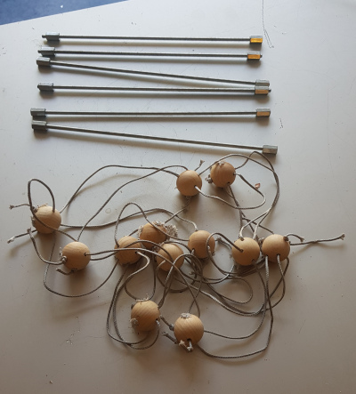
First thing was to collect the materials together.
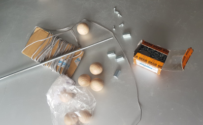
- non-stretchy cord - Dyneema 2mm
- wooden balls - 30mm diameter
- threaded rod - M6
- connecting nuts - longer than usual nuts
- screws - 3mm x 12mm
Where to drill?
Drilling spherical balls is a little tricky because of their shape, but before the drilling could begin it needed to be clear where to put the holes.
I used the virtual model to calculate chord lengths, each chord being the straight line distance through the ball from one hole to the next. Using all the chords I was able to triangulate, scratching arcs from existing markings and making new markings where the scratches crossed.
I had the software give me every chord length so I could even double-check my measurements by measuring pairs that I didn’t need for the original triangulation. It’s a challenge to communicate sphere measurements from the software into the real world, so I was happy with this redundancy!
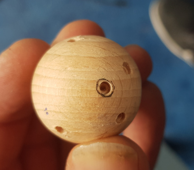
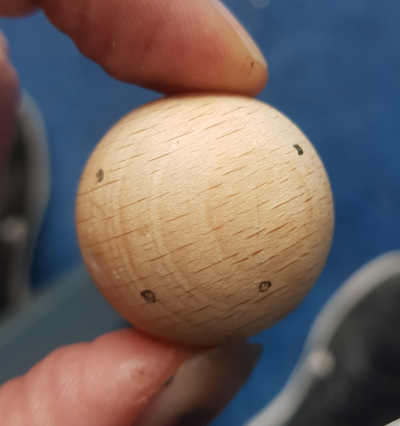
So there I had one ball, carefully measured and marked, and I drilled slight holes in it to suggest the hole entrances. But that’s just one ball! I needed 12 of them drilled exactly the same way, but the time it would have taken to do all that by triangulation was not attractive. I had to find a shortcut.
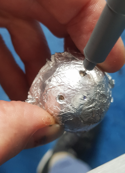
I decided to make a kind of mold, out of several layers of aluminum foil stuck together with gradually hardening epoxy glue, because this way I could bend the surface around my one prepared ball and press hard to reveal the proto-holes, and then let it harden in the concave-spherical shape.
The result was this little guy:
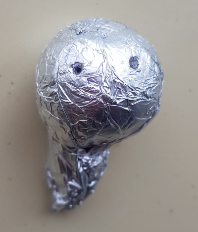
After the underlying holes appeared, I pricked them through and then waited for the glue to get hard. Then it was time to open him up so I could re-use the pattern of hole locations that he had captured.
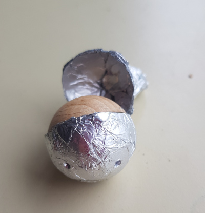
Pushing back the edges so it became a half-sphere gave me the marking mold that I needed. Inserting each of the other balls into the mold, I was able to make marks on all of the other balls without needing to redo the time-consuming triangulation-with-chords trick.
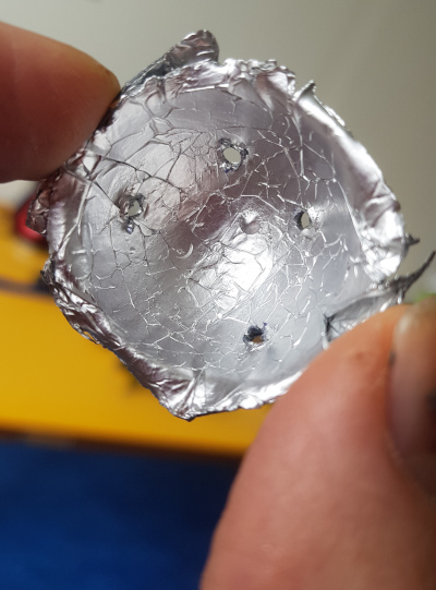
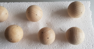
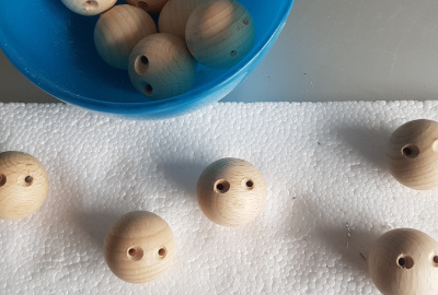
Soon afterwards I had all the balls marked.
Drilling
This is the point at which I first stumbled, because I drilled the first set of balls all the way through for each of the 4 holes. That made the holes all meet in the center of the sphere, and after a bit of frustration I concluded that getting 4 cords to pass each other inside was just too difficult.
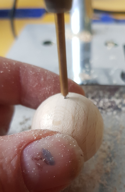
To solve the center cord conflict, I decided to try and drill the two nearest holes parallel to each other, rather than through the center of the ball.
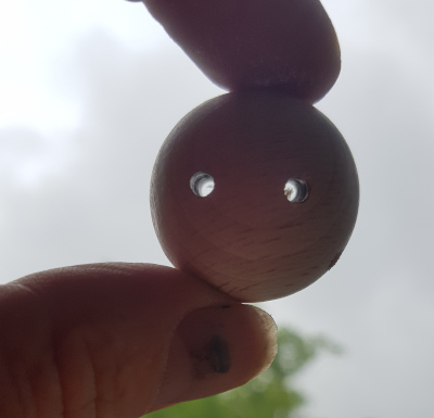
To accommodate the screws I even made countersinks at the opposite ends of the holes.

Threading
With the two parallel “eye” holes, I was able to get the cords through without any problem. There is still potentially a cord crossing, but it can only involve pairs of cords, and it’s easy to let two cords pass each other.
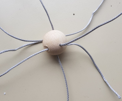
The next challenge is to feed all 24 Dyneema cord segments through the correct pairs of holes such that the tension network is connected and all of the joints are oriented correctly relative to the network. This was also more difficult than expected, because it’s remarkably hard to keep track of everything.
To make it easier, I used an existing tensegrity structure as a scaffolding, and stuck everything in the right place with tape. Tricky stuff, so there’s much room for innovation here.
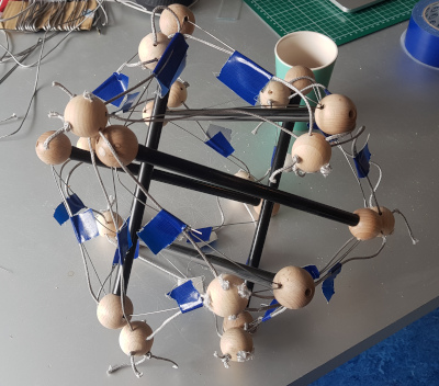
After this initial threading I had each cord segment strongly fixed with a screw on one end, but only threaded through the other end with a loose knot to keep it from escaping.
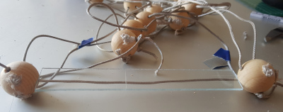
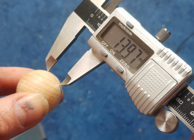
The next step was to precisely measure all of the ball-to-ball distances, which all had to be exactly the same within a millimeter or two, so for that I cut a little ruler out of plexiglass of the precise length. With the plexiglass holding the length right, I carefully cut the cords to length and wiggled more screws into the hollow cord, finally tightening them all up.
Tension, meet Compression
Finally, with all the cord segments fixed at the right length, each one ready to hold two balls at the assigned distance, it was time to introduce the compression struts.
Each strut consisted of a 30cm segment of threaded rod, with a long connector nut at each end. The rods were intended to just fit snugly by themselves, and then the nut could be used to effectively lengthen the rods by a few percent to pretense the structure afterwards.
It turned out to be easier once I hung the tension network from a cord so that I could insert the rods one by one. The rods are not connected to the balls so it was a beautiful thing to observe the tensegrity taking shape with each of the rods only pushing on a pair of balls.
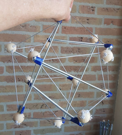
A few turns of each of the nuts made it possible to tighten things up until it felt a little bit like the cords were guitar strings.
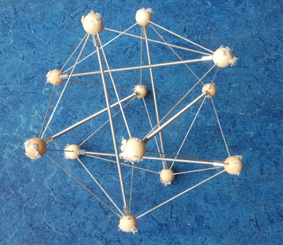
Hello Prefab Tension!
It worked! Here was the first example that I’ve ever had in my hands of a tensegrity where the tension network was created while slack, and the compression struts indroduced and tightened later!
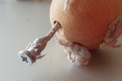
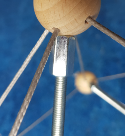
Zooming in on one of the tensegrity’s tension triangles, the beautiful spiral of pushing force from the bars appears. (The furry parts are just the extra unwoven dyneema fibers which surround each of the screws)
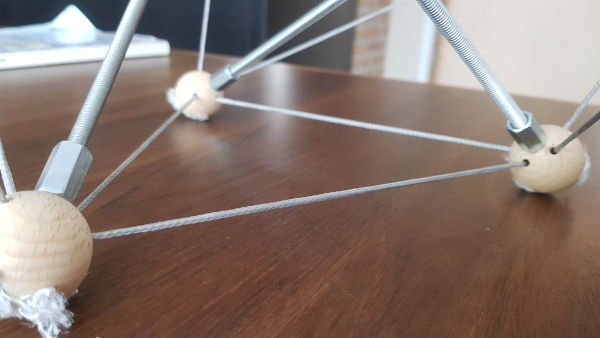
Every ball is ever so slightly captured by its spherical surface being nested in the concavity of the nut’s hole after the strut is lengthened.
Conclusion
In your hands the structure feels a bit like magic because it’s remarkably tight, so I have to say: mission accomplished! The process was a bit too tricky, though. Several aspects may lend themselves to simplification, so that will have to be the focus of a future construction.
Projects:
2024-07-23: "Bouncy Wooden Sphere": what you can do with a discarded bed2024-04-23: "Twisted Torque": tied into a permanent twist
2023-03-27: "Easy 30-Push Sphere": one simple element
2022-10-05: "Glass and LED": going big and colorful
2022-09-29: "Fascia": dancing with tensegrity
2022-08-30: "Mitosis": the four-three-two tensegrity
2022-08-04: "Push Bolts for the People": finalizing design and getting it out there
2022-06-22: "Head to Head Push Bolt": M5 and M6 bolts symbiosis
2022-05-30: "Hiding Knots": bump up the aesthetics
2022-05-25: "Innovation with 3D Printer": the push bolt
2021-12-02: "Headless Hug": breaking a rule for the sake of symmetry
2021-10-28: "Rebuilding the Halo": finally got it right
2021-10-20: "Convergence": growing and reconnecting
2021-07-27: "120-Strut Brass Bubble": taking the next step up in complexity
2021-05-26: "30-Strut Brass Bubble": bouncing spherical tensegrity
2021-04-08: "Bow Tie Tensegrity": better bend resistance
2021-03-29: "Six Twist Essential": what if more hands could see?!
2021-01-25: "Minimal Tensegrity": no more tension lines than absolutely necessary
2021-01-18: "Degrees of Freedom": first adjustable hybrid tensegrity
2021-01-11: "Fractal Experiment": a tensegrity of tensegrities
2020-12-09: "Axial Tension": pretensing what is already pretenst
2020-11-02: "Halo by Crane - Part 2": the strengthening
2020-10-26: "Halo by Crane - Part 1": assembly complete but strength lacking
2020-10-12: "Brass and Tulips": a tight and strong tensegrity tower
2020-08-10: "Prefab Tension Tower": the tower of eight twists
2020-07-27: "Elastic Bubble": building with elastic ease
2020-07-13: "The Twist Sisters": left-handed and right-handed
2020-07-06: "Radial Tension": Pulling towards the middle
2020-06-22: "Diamond of Tension": Four pulls for every push
2020-06-15: "Prefab Tension": Separating compression from tension